
|Articles|December 1, 2006
As era of 3T MR takes hold, new opportunities emerge
Author(s)William G. Bradley Jr., MD, PhD
Like an expanding bubble, the number of MR applications continues to rise exponentially. Looking back over the last 27 years, I see several major MRI epochs: low- to midfield systems (late 1970s to mid-1980s), 1.5T with 10 mT/m gradients (mid-1980s to mid-1990s), and 1.5T with echo-planar gradients (mid-1990s to early 2000s). We entered a new epoch a few years ago: 3T with echo-planar gradients. Examining changes currently occurring, and understanding why they occur, can help us predict further changes to come over the next decade.
Advertisement
I have had the good fortune of being involved with MRI since the end of my first year of residency at the University of California, San Francisco in 1979. Over the last quarter century, whenever I thought MRI technology had plateaued, out came another application. Like an expanding bubble, the number of MR applications continues to rise exponentially.
Looking back over the last 27 years, I see several major MRI epochs: low- to midfield systems (late 1970s to mid-1980s), 1.5T with 10 mT/m gradients (mid-1980s to mid-1990s), and 1.5T with echo-planar gradients (mid-1990s to early 2000s). We entered a new epoch a few years ago: 3T with echo-planar gradients. Examining changes currently occurring, and understanding why they occur, can help us predict further changes to come over the next decade.
The first 3T magnets were introduced 10 years ago. Despite the better spatial resolution, early users such as Dr. Jeffrey S. Ross at the Cleveland Clinic were not thrilled. In fact, he wrote a fairly scathing editorial against 3T just three years ago in the American Journal of Neuroradiology.1 So why the stampede to 3T now? What changed? What changed was the appearance of two synergistic technologies: parallel imaging and phased-array coils.
Parallel imaging is also known as SENSE (Philips Medical Systems), ASSET (GE Healthcare), or iPAT (Siemens Medical Solutions). In order to do it, you need phased-array coils. Besides enabling parallel imaging, phased-array coils increase the signal-to-noise ratio. A typical eight-channel phased-array coil increases SNR 40%, independent of field strength. A prototype 32-channel head coil developed at Massachusetts General Hospital increased SNR in the cortex 3.5 times and that in the center of the brain almost 1.4 times.2 Parallel imaging allows users to trade off the extra SNR of 3T to go faster. Since 3T has roughly twice the SNR of 1.5T, it permits better spatial resolution and/or thinner slices. Users can go four times faster with the same spatial resolution and slice thickness, as long as they have at least four coil elements in the phased array.
HOW PARALLEL IMAGING WORKS
If you cover every other line of k-space, the acquisition time is halved but so is your field-of-view, leading to aliasing or wraparound. By knowing the local sensitivity of each coil in the phased array, you can "unwrap" the image.
For the first time, unenhanced 1024 x 1024 (matrix) MR angiography of the brain becomes possible (Figure 1). Actually, by using a 1024 x 680 matrix over a 16 x 12-cm field-of-view, 160 x 200-micron pixels can be produced. This compares with 250-micron resolution for digital subtraction angiography. The 100-micron-diameter ophthalmic and lenticulostriate arteries are now commonly seen.
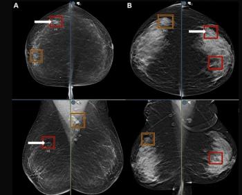
MRI of the breast can be performed with greater spatial resolution and thinner slices. Breast cancer that might appear smoothly marginated, and thus benign, on a 256 x 256 1.5T scan would have a greater chance of appearing spiculated on a 512 x 400 matrix at 3T (Figure 2).
Since T1 increases with field strength, the amount of T1 weighting (measured by the ratio TR/T1) will increase at constant TR, as will contrast enhancement. Greater T1 weighting will also lead to greater flow-related enhancement3 and allow better noncontrast perfusion imaging using arterial spin labeling.4
Magnetic susceptibility effects such as those due to acute hemorrhage (deoxyhemoglobin) are more obvious at 3T. This sensitivity basically doubles the blood oxygen level-dependent effect, which is the basis for functional MRI. Since MRI is likely to be used for acute stroke triage in the future, it must be able to do what is currently done by CT: exclude hemorrhage. As described above, 3T MRI is exquisitely sensitive to acute hemorrhage. Since it can also perform diffusion and perfusion imaging on the entire brain, while 64-slice CT cannot do diffusion at all and can cover only 4 cm of brain for perfusion, MRI should replace CT for this purpose in the future. We will be placing 3T MR scanners near the emergency departments of both of our university hospitals over the next one to two years.
While 3T is also more sensitive to diamagnetic susceptibility artifacts, parallel imaging can be used to decrease these. With echo-planar diffusion and perfusion imaging, the large artifacts over the petrous bones result from the difference in diamagnetic susceptibility between air and water. These tend to be worse at 3T, but parallel imaging can be used to decrease the TE, reducing the diamagnetic susceptibility artifacts to 1.5T levels.
Chemical shift artifact between fat and water doubles in the move from 1.5T to 3T, all else (e.g., bandwidth) staying the same. Thus, use of STIR and fat saturation will probably be increased at 3T. The flip side of increased chemical shift artifact is increased spectral separation in MR spectroscopy.
In MRS, the SNR and spectral separation are twice at 3T what they are at 1.5T. The first property will allow smaller voxels and improved spatial resolution, down to ~5 mm for 3D techniques. The second may allow us to see species such as glutamate not currently seen. Glutamate, released by 90% of the excitatory neurons in the brain, is involved in memory, learning, and neurodegeneration. Being able to quantitate glutamate will be a huge step. Glutamate is broken down to glutamine, but, unfortunately, the two are tightly coupled spin systems currently combined as one low SNR peak labeled Glx. The spin coupling and loss of peak height increase with TE. In order to see glutamate separately from glutamine, the TE must be less than 5 msec, which is not currently possible on commercial scanners but has been achieved in a research setting.5
While 3T brings many advantages, it also has potential problems. Radiofrequency heating is four times greater at 3T compared with 1.5T. For sequences like fast spin-echo, the increased RF heating could exceed the FDA's specific absorption rate limits. But tricks to decrease RF heating are available. The 180o refocusing pulses, for example, can be reduced to 125o. The magnetization transfer pulses that are part of every MR angiogram of the brain increase RF heating but can be limited to the central 20% of k-space, reducing the SAR by 80%.
One problem that hasn't been entirely solved yet is the banding on body images due to standing waves from dielectric effects. This leads to local bright or dark stripes, which can be reduced with dielectric pads. While this remains a problem, 3T body images are still better than those at 1.5T, according to our chief of body MRI. Double-contrast livers with ultrasmall superparamagnetic iron oxide particles and gadolinium are definitely superior to anything at 1.5T for characterizing cirrhosis (Figure 3).
While some minor problems with 3T may be a challenge, I am reminded of that period 10 years ago when echo-planar units first came out. I purchased my first EPI upgrade knowing only that we would be able to scan in 100 msec. I had no idea that EPI diffusion, which we now do on every brain, and EPI perfusion, which we try to do on every contrast-enhanced brain, were in the wings or that the strong, fast gradients required for EPI would also enable the short TR and TE required for contrast-enhanced MRA.
Thus, whenever you are at a technology inflection point, as we are now with 3T, I would urge you to adopt the new technology even if you can't fully justify the added cost-yet. New applications will come along as they did for the systems with EPI gradients. Staying with current technology just means you will be married to the equivalent of a 0.5T system for the next 10 years.
NEW TECHNIQUES
Ultrashort TE (UTE) was first described almost 15 years ago by John Pauly, a professor of electrical engineering in the information systems laboratory at Stanford University. Prof. Graeme Bydder of STIR and FLAIR fame started working with the UTE technique almost five years ago when he was at Hammersmith Hospital in London, and he has shifted the work to 3T since moving to UCSD three years ago.
When most of us think short TE, we think 1 msec or so with a fractional echo; that is, a partial Fourier in read. Bydder is down to a TE of 8 microsec! At that short a TE, you can pick up signal from short T2 solids. Tissues with short T2s also have short T1s, so calcium and cortical bone appear bright on UTE images due to rapid T1 recovery.
Bydder has applied this technique to see the calcified deep layer of cartilage (Figure 4). Normally, this layer is dark and merges imperceptively with cortical bone. Since it has a short T1, it appears bright, so it can now be seen directly. This is significant because many arthridites start in the calcified deep layer of cartilage. This objective method to image early arthritis requires imaging the deep layer can be done only by UTE.6
Motion has been a major cause of artifact in MRI. Several years ago, Jim Pipe, senior staff scientist in the MRI department at the Barrow Neurologic Institute, introduced a technique called Propeller, which samples k-space in a radial rather than the usual rectilinear fashion.7 If motion occurs, the high-intensity dots representing the center of k-space can be realigned, eliminating the motion artifact. Although 100-msec EPI diffusion techniques are relatively immune to motion, they are susceptible to diamagnetic susceptibility artifacts over the petrous bones. Combining diffusion imaging with a fast spin-echo readout minimizes these susceptibility effects, although it takes longer. Further combination with Propeller eliminates motion artifacts (Figure 5).
Several other techniques are enhanced at 3T:
MR-guided focused ultrasound. High-intensity focused ultrasound (HIFU) has been around for half a century, but there has never been a way to measure the temperature rise. In order to kill tissue, the temperature has to be at 60oC for at least a minute. MR can measure temperature changes based on the phase shift on a gradient-echo image. When HIFU is performed under MR guidance, it is known as MR-guided focused ultrasound (MRgFUS). This is a new technique that enables the thermal ablation of tumors throughout the body without breaking the skin.
A major application for MRgFUS is fibroid ablation (Figure 6). Women with symptomatic fibroids have a choice of hysterectomy, which is expensive and painful and requires a long recovery; uterine artery embolization, which is somewhat less expensive but still painful; and MRgFUS. Many women making the third choice are out riding a bicycle or a horse on the afternoon of their MRgFUS procedure.
In addition to fibroid ablation at 1.5T (FDA-approved) and 3T (FDA approval pending), MRgFUS can be used to ablate benign and malignant breast tumors and bone tumors. Recent work in Dr. Ferenc Jolesz's lab at Brigham and Women's Hospital in Boston has focused on MRgFUS of the brain. Since 90% of the ultrasound energy is reflected back by the calvarium, a waterbag heat sink has been added. Deep-seated tumors can be zapped without cracking the skull or breaking the skin. Glioblastoma multiforme can be palliated. Low-grade gliomas can potentially be cured. Since no radiation is involved, radiation necrosis that occurs with gamma knife and other radiosurgery techniques should be avoided.
When MRgFUS of the brain is run in low power mode, the blood-brain barrier can be temporarily opened, according to a recent finding.8 This could be important for patients with epilepsy (1% of the population). If magnetoencephalography is used to localize the initial seizure focus to within a centimeter, that region of the brain can be swept with low-power MRgFUS, temporarily opening up the blood-brain barrier. If an intravenous drip is going with Versed-laden liposomes, the MRgFUS would both open up the blood-brain barrier and lyse the liposomes, putting that point of the brain to sleep. If an EEG shows a drop in the seizure spike, the MRgFUS energy can be turned up to zap the seizure focus.
Intraoperative MRI. MR has played a role in the operating room to monitor brain tumor resection since the initial 0.5T double-donut system was installed at the Brigham over a decade ago.9 The major finding at the Brigham and at Long Beach Memorial when I was there was that 80% of the time a neurosurgeon thinks a gross total resection has been achieved, MR-visible tumor remains to be removed. For low-grade gliomas, getting all the tumor out amounts to a complete cure. If even a small nodule is left behind, however, it will eventually degenerate into a glioblastoma multiforme, which currently has no cure.
While complete cure of a brain tumor is important to the individual patient, not that many new glioma patients emerge each year (maybe 20,000 low-grade tumors), and this is not a large market for vendors. They need a more common disease that can be cured only with intraoperative MRI. An exciting prospect being developed at UCSD by neuroscientist Dr. Mark Tuszynski is use of gene therapy (nerve growth factor) to treat Alzheimer's and Parkinson's diseases.10 To have a favorable effect in Alzheimer's and Parkinson's, however, the nerve growth factor must be deposited exactly in the nucleus basalis and the subthalamic nucleus, respectively. If it is deposited a few millimeters away from the target, the outcome can be negative rather than potentially positive.
Current techniques are based on frame-based stereotaxy, which has two problems. The first is the brain shift that occurs following the burr hole and leakage of cerebrospinal fluid. The second is that the performance of stereotaxy in Tallairach space is based on the brain of one alcoholic 40-year-old Frenchwoman. Performing the procedure under direct visualization using intraoperative MRI will ensure proper localization of the injection of the gene therapy today and the stem cell therapy tagged with superparamagnetic iron oxide particles (SPIO) in the future.
Nonuniform Bo MRI. Thirty years ago, clinical ultrasound units were large, cumbersome, expensive consoles with articulated arms. Today they are portable and cheap. The same evolution could happen with MRI. The most expensive part of the MR system is the magnet, which is wound and shimmed to produce a very uniform main magnetic field (Bo). MagneVu (Carlsbad, CA) has been working with cheap nonuniform Bo magnets. A prototype handheld MRI was produced several years ago. The technology has already been commercialized for in-office portable MR scanning of arthritis by rheumatologists. The 3D STIR images produced (Figure 7) are clearly superior to plain films for detecting early synovitis or changes with treatment.
Hyperpolarized carbon-13 MR spectroscopy. One of the most exciting prospects on the horizon is hyperpolarized C-13 MR spectroscopy. While hyperpolarized helium and neon have been used in the research environment for lung imaging, hyperpolarized C-13 gives us the opportunity to rapidly evaluate not only the structure but the metabolism of a tissue. Hyperpolarization refers to a process whereby the spins can acquire up to 100,000 times more signal than that achievable with conventional scanning.
Since there is no background signal, the SNR is extremely high, allowing rapid temporal spectroscopy at high resolution. There are two techniques for hyperpolarizing C-13: one using parahydrogen (the dominant form of hydrogen at low temperatures) and the other known as DNP (dynamic nuclear polarization), which involves doping hydrocarbon compounds with paramagnetic species and then separating them out before injection.
Each technique has its pros and cons. But using either technique will eventually make it possible to measure the kinetics as, for example, pyruvate is metabolized to lactate. Distinguishing normal from neoplastic tissue will potentially become possible.
Dr. Bradley is chair of radiology at the University of California, San Diego. He has received departmental support from GE Healthcare and is a consultant for GE and a participant in GE's speakers' bureau.
References1. Ross JS. The high-field-strength curmudgeon. AJNR 2004;25:168-169.
2. Wiggins GC, Triantafyllou C, Potthast A, et al. 32-channel 3 Tesla receive-only phased-array head coil with soccer-ball element geometry. Magn Reson Med 2006;56(1):216-223.
3. Bradley WG, Waluch V. Blood flow: magnetic resonance imaging. Radiology 1985;154:443-450.
4. Wong EC, Cronin M, Wu WC, et al. Velocity-selective arterial spin labeling. Magn Reson Med 2006;55(6):1334-1341.
5. Knight-Scott J, Shanbhag DD, Dunham SA. A phase rotation scheme for achieving very short echo times with localized stimulated echo spectroscopy. Magn Reson Imaging 2005;23(8):871-876. Epub 2005 Oct 13.
6. Gatehouse PD, Thomas RW, Robson MD, et al. Magnetic resonance imaging of the knee with ultrashort TE pulse sequences. Magn Reson Imaging 2004;22(8):1061-1067.
7. Forbes KP, Pipe JG, Karis JP, Heiserman JE. Improved image quality and detection of acute cerebral infarction with PROPELLER diffusion-weighted MR imaging. Radiology 2002;225(2):551-555.
8. Hynynen K et al. Noninvasive MR Image-guided focal opening of the blood brain barrier in rabbits. Radiology 2001;220:640-646.
9. Black PM, Moriarty T, Alexander E 3rd, et al. Development and implementation of intraoperative magnetic resonance imaging and its neurosurgical applications. Neurosurgery 1997;41(4):831-842; discussion 842-845.
10. Tuszynski MH, Thal L, Pay M, et al. A phase 1 clinical trial of nerve growth factor gene therapy for Alzheimer disease. Nat Med 2005;11(5):551-55. Epub 2005 Apr 24.
11. Goldman M, Johannesson H, Axelsson O, Karlsson M. Hyperpolarization of 13C through order transfer from parahydrogen: a new contrast agent for MRI. Magn Reson Imaging 2005;Feb;23(2):153-157.
Advertisement
Related Content
Advertisement


Advertisement
Advertisement
Trending on Diagnostic Imaging
1
Study Suggests FDG-PET Better than CT for Assessing Treatment Response for Metastatic Breast Cancer
2
Mammography Study Suggests AI Can Bolster the Ability of General Radiologists to Detect Breast Cancer
3
A Closer Look at the Evolution and Emerging Insights with Amyloid and Tau PET for Dementia and Alzheimer’s Disease
4
Could an Emerging Ultrasound Device Facilitate More Efficient Vascular Access Workflows?
5